Cross-perforated plates (plates with cruciform or “cross” shaped punches) combine visual character with functional advantages — from acoustic panels and sunshades to safety grating and filtration. Their unusual geometry changes how stress flows through the sheet compared with simple round or square holes. This article walks through hole-pattern geometry, how stress concentrates and spreads around cross holes, material and thickness tradeoffs, practical design tips for production, and suggestions you can apply right away to optimize strength and lifetime.
Why hole-shape matters
Hole shape determines three things that matter for engineers and buyers:
- Mechanical behavior: corners and sharp transitions (like the arms of a cross) create local stress concentrations.
- Open area and airflow: a cross shape can provide a higher visual open area per unit than some patterns, or a tailored directional opening.
- Manufacturability and finish: complex punches need heavier press forces and careful tooling to control burrs and deformation.
When you compare a round perforated metal plate to a cross perforated metal plate, the round hole tends to distribute stress smoothly, while the cross concentrates it where arms intersect the web. Recognizing those differences lets you design safely without over-engineering material thickness.
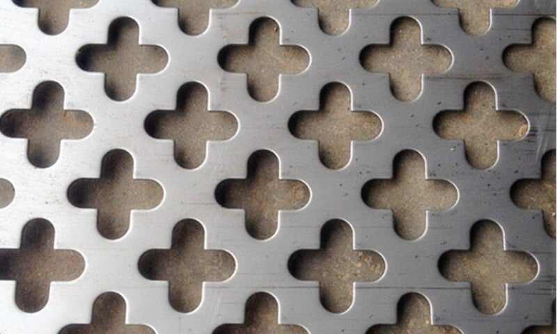
Geometry and key parameters
Designing a cross pattern starts with a few basic parameters:
- Arm width (w): thickness of each cross arm.
- Arm length (l): how far each arm extends from the center.
- Corner radius (r): the radius where the arm meets the web — rounding here reduces stress concentration dramatically.
- Pitch (p): center-to-center distance between adjacent crosses — governs open area and remaining material.
- Sheet thickness (t): interacts with hole size to determine stiffness and buckling resistance.
- Open area (%) = (area of all crosses per repeating cell) / (cell area) × 100.
Practical rule: increase corner radii and arm widths when the load path crosses many holes, and increase pitch (more metal between holes) when you need higher stiffness.
Stress distribution — what to expect
Basic behavior
Cross holes produce localized stress risers where the arms meet the web. Under tensile load, stress lines funnel through the remaining metal and concentrate at the root of each arm. Under bending, the side of the sheet near the neutral axis shifts load paths in different ways, sometimes reducing tensile concentrations but increasing shear where arms intersect.
How to reduce critical stress
- Round the arm roots (increase r): a small radius added to the intersection of arm and web reduces peak stress more than increasing thickness in many cases.
- Avoid very thin webs between adjacent crosses — keep at least 1.5–2× the sheet thickness for web width when the plate will carry structural loads.
- Stagger patterns so stress paths aren’t continuous lines of weakness. A staggered grid interrupts continuous high-stress corridors.
- Select the right material: ductile alloys tolerate local plasticity better than brittle ones.
H2 Material and thickness choices
Material choice changes how a given cross pattern behaves:
- For corrosive or hygienic environments consider a stainless steel perforated metal plate. It will yield different fatigue and post-punch residual stress than carbon steel.
- If you need lighter weight with decent formability, an aluminum perforated metal plate is attractive but requires wider webs or thicker gauges to match stiffness.
- For heavy-duty wear or impact, manganese steel perforated plates or thicker carbon steel perforated plates are common choices.
- For outdoor applications where surface protection is needed, a galvanized perforated metal plate adds corrosion resistance.
Thickness interacts with hole geometry. Thin sheets (≤1.5 mm) are economical and punch cleanly for decorative or acoustic uses, but for load-bearing panels, thicknesses from 2 mm upward (depending on span and load) are typical.
Manufacturability and tooling considerations
- Punch quality matters. Cross punches must be sharp and well supported to avoid burrs and distortion. Controlled tooling clearance reduces burr height.
- Progressive dies vs. single-station punching. Complex cross shapes often benefit from progressive tooling to reduce deformation.
- One-off vs. mass production. We support one-piece prototypes and large batches; for high volume the die investment pays off and part quality improves. (See our options for perforated safety grating and custom builds.)
- Edge finishing. Deburring, passivation (for stainless), or coating help if the plate will be handled or used in exposed installations.
Practical design guidelines (checklist)
- Add a fillet radius at arm roots: r ≥ 0.5t (sheet thickness) as a starting point.
- Keep web width between neighboring crosses ≥ 1.5t for moderate loads, ≥ 2t for structural loads.
- Limit arm aspect ratio (length/width) so arms don’t become too slender—aim for l/w ≤ 4 when possible.
- For repeated loading or vibration, choose a more ductile material and increase radius; consider fatigue testing for critical components.
- If acoustic or airflow properties matter, prototype with a 1:1 printed template to confirm open area and visual effect before committing to tooling.
Examples and where cross patterns shine
Cross patterns are particularly useful when you want a balance of:
- Distinctive aesthetics (facades, interior screens),
- Directional airflow (vents that favor one direction), and
- Grip or drainage (flooring, platforms).
For filtration or very fine openings, consider micro-perforated metal plate instead; for heavy duty load paths, pair cross patterns with thicker gauges or use them as overlays on structural backing.
Final thoughts
Designing cross-perforated plates is a balance: the unique geometry delivers aesthetics and functional benefits but shifts stress and manufacturing needs. Small design choices — fillet radii, web width, material selection, and pattern pitch — have outsized influence on durability and cost. Start with the simple checklist above, prototype (or request a sample), and adapt the pattern to your load and aesthetic goals.
If you want a quick feasibility check for a specific cross pattern (material, thickness, pitch), send your basic specs to info@perfsheet.com. We can provide sample recommendations, discuss single-piece prototypes or volume tooling, and quote production lead times.
Contact: info@perfsheet.com