Introduction — strength-first hole patterning
This short technical note explains why hole geometry is an engineering decision, not decoration, when designing custom heavy duty perforated plate hole patterns for structural and long-service industrial applications. Engineers and buyers specifying thick, load-bearing panels must balance open area, material ligament, edge distance, and punching/manufacturing feasibility to avoid local weakness, distortion, or premature fatigue.
Key strength variables to control
- Open area (percent): determines airflow/weight removal but reduces cross-sectional material for load transfer.
- Ligament (web) width: the remaining metal between holes; directly controls local bending and shear capacity.
- Edge distance / margin: distance from hole centers to sheet edge or cutouts — critical for avoiding tear-out under bearing loads.
- Plate thickness: for these applications use the project’s thickness schedule (e.g., 2.75–30 mm) to preserve global stiffness and local bearing strength.
- Manufacturing effects: punching, leveling/flattening, laser cutting, and heat input from secondary operations all alter local microstructure and residual stresses.
Important production facts (for spec cross-checks): typical max sheet handling is up to 6000×1500 mm, and available materials include Q345, mild steel, stainless, aluminum, and high manganese steel. Keep these constraints in your procurement and engineering checks.

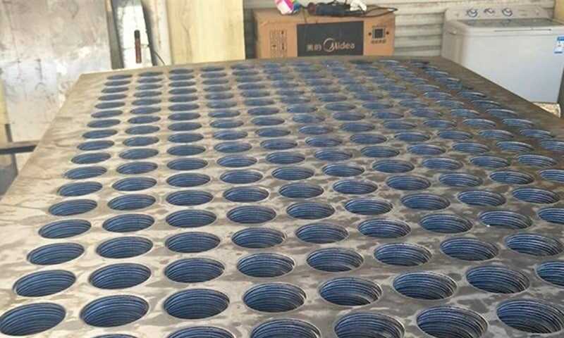
Heavy Duty Perforated Plates
Need a thick perforated plate made to drawing? Our program supports 2.75–30mm thickness, up to 6000×1500mm, with round/square/hex/slotted patterns, plus cut-to-size and surface protection for industrial installations.
Design rules of thumb (qualitative)
- Prioritize continuous load paths: avoid hole layouts that create a narrow continuous strip of ligament across a load span.
- Maintain balanced open area: cluster holes for ventilation or weight savings only where those areas are not primary load paths.
- Consider manufacturing: dense hole packs in thick plates increase punch/load on tooling and may require laser or waterjet rather than conventional punching.
- Plan for finishing: heavy plates often need flattening/leveling after punching to meet flatness and assembly tolerances.
How hole type influences strength and manufacturability
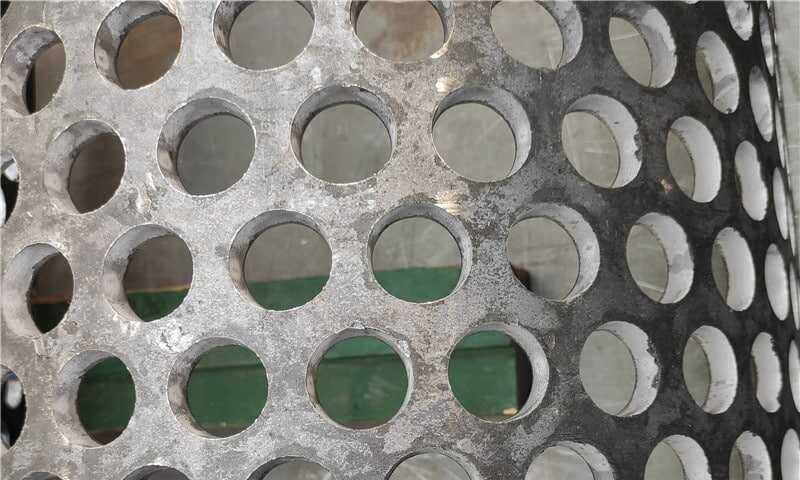
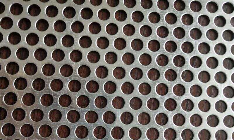
Round holes — proven, predictable
- Applicability: Best for general load-bearing panels where uniform stress distribution and simple punching are required (vents, guards, access covers). Round holes maintain consistent ligament geometry in all directions.
- Risk point: High open area with round holes can create continuous thin ligaments that concentrate bending; avoid long uninterrupted rows in primary load paths.
Hexagonal holes — high open area with caveats
- Applicability: Useful when maximizing open area per unit material is critical (screening, ventilation) while retaining more shared ligament than equivalent circular layouts.
- Risk point: Hex patterns can create short, directional ligaments that concentrate shear in localized bands; in thick, heavy plates this may create stress risers at pattern junctions.
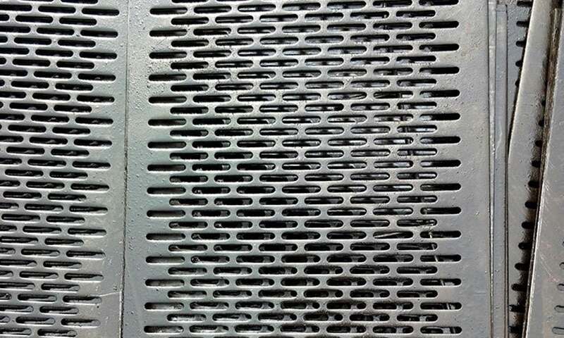
Slotted holes (elongated) — alignment and flow advantages
- Applicability: Good for adjustable mounting slots and directional airflow. Slots reduce stress concentration at mounting holes and ease installation.
- Risk point: Slotted patterns remove more continuous material along one axis; when aligned with the primary load direction they can severely reduce bending capacity — stagger or rotate slots relative to primary loads.
Other shapes (square, rectangular, custom shapes)
- Applicability: Chosen for specific functional or manufacturing reasons (interlocking, aesthetic masking).
- Risk point: Corners and sharp internal geometry increase local stress concentrations — consider radius reliefs or alternative shapes where high fatigue or bearing loads exist.
Practical examples (one-line use case + risk)
- Round: Equipment guard with moderate point loads — risk: narrow continuous ligament if hole spacing too tight.
- Hex: Vent screen maximizing airflow in a marine intake — risk: localized shear bands at pattern vertices.
- Slotted: Adjustable platform brackets — risk: reduced bending stiffness if slots align with span.
Manufacturing & QA checklist
- Verify thickness and material: match structural demands (use provided thickness range 2.75–30 mm).
- Confirm maximum sheet size with supplier when planning large panels.
- Request sample flatness and a punch-quality coupon for dense patterns.
- Require post-punch leveling/flattening and dimensional inspection for assembly interfaces.
- Specify surface protection (sandblasting/coating) if environmental corrosion is expected.
Engineering review steps (recommended)
- Map primary load paths and mark zones where open area is permissible.
- Select hole type to match function (venting, weight saving, mounting).
- Run finite-element checks or simplified strip analysis on critical spans.
- Coordinate with manufacturer on punch method, tool life, and flattening process.
- Update drawing notes with minimum edge distances and assembly tolerances.
Procurement note
When you write the purchase specification, call out hole pattern type, center-to-center pitch, minimum ligament, plate thickness, and required post-punch leveling. If you need a proven supplier for heavy, industrial perforated panels, reference the project requirement for a heavy duty perforated plate or a specific thick perforated plate option in your RFQ so vendors size tooling and process planning correctly.
Conclusion
Hole geometry directly changes load distribution and durability in heavy-gauge perforated plates. For thick, load-bearing applications prioritize ligament continuity, edge distance, and manufacturing method over maximizing open area. Treat pattern selection as part of the structural design — not just a cutting operation — and validate critical spans with calculation or test pieces before committing full production.