Introduction — why this matters for buyers and engineers
In heavy-duty applications (structural grating, machine guards, filtration support, walkways, and heavy equipment panels), the decision about hole pattern isn’t aesthetic — it’s engineering. The tradeoff is always between open area (ventilation, drainage, weight savings) and material bridges (ligaments) that carry loads and resist fatigue. Below I’ll walk through practical rules-of-thumb, the math you need, and worked examples you can use in procurement specs and engineering checks.

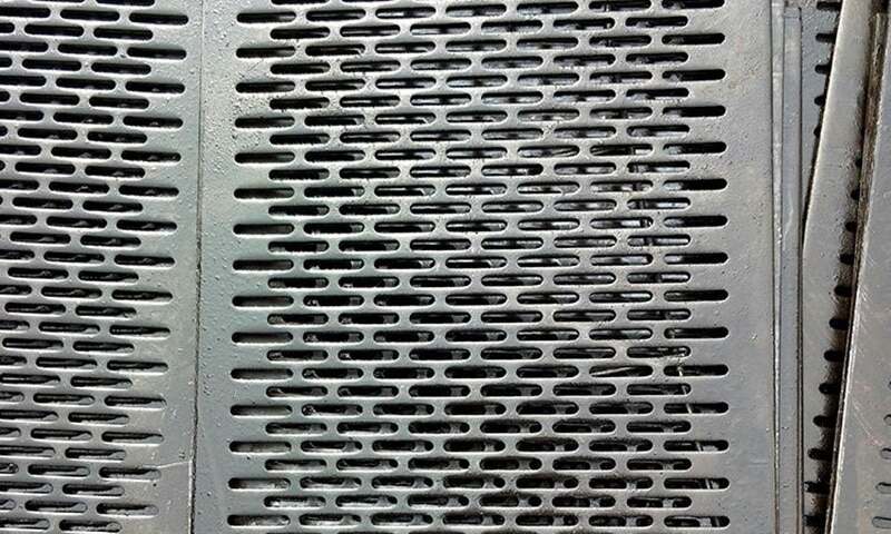
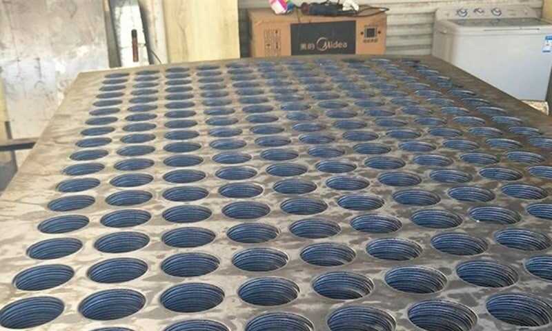
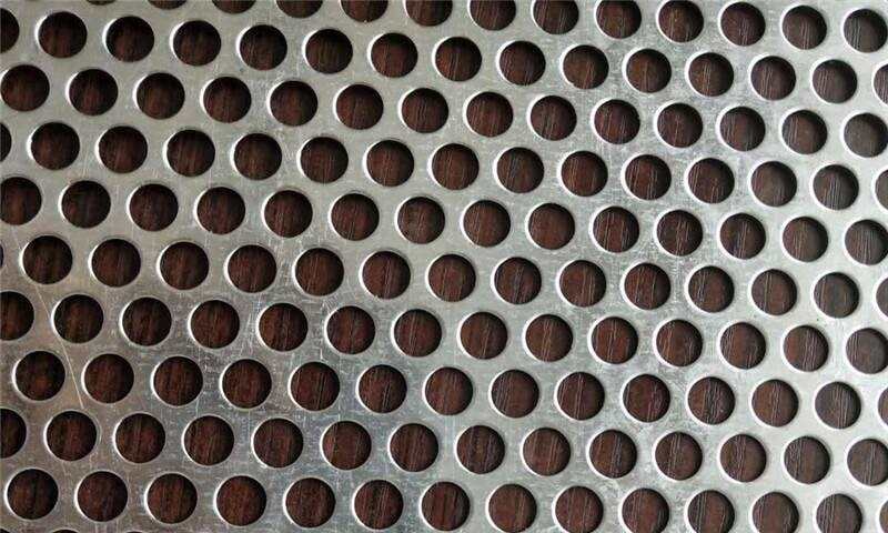
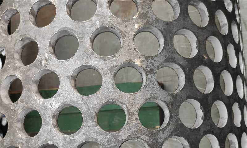
Heavy Duty Perforated Plates
Need a custom heavy-duty perforated plate?
We offer perforated plates with thickness ranging from 2.75mm to 30mm, and up to 6000×1500mm in size, available in round, square, hexagonal, and slotted patterns.
Additionally, we provide precise cutting, surface protection, and other processing services tailored to meet industrial installation requirements.
Feel free to contact us anytime, and we’ll provide a personalized solution that perfectly matches your project needs.
Key concepts — what to measure and why
Open area (definition)
Open area (%) = (total area of holes ÷ total sheet area) × 100.
Higher open area → better airflow and lower weight. Lower open area → more continuous material and higher local stiffness/strength.
Ligament (material bridge) width
Ligament (bridge) width = pitch (center-to-center) − hole diameter.
This simple geometric number is the primary control on the local load path for a perforated plate.
Pattern types that matter
- Square (orthogonal) grid — holes aligned in rows/columns. Easier to punch and common for heavier plates.
- Staggered / hexagonal grid — higher open area for the same pitch, but ligaments are oriented differently and tooling considerations differ.
Useful formulas (copy into a datasheet)
All formulas assume hole diameter d and center-to-center pitch p, both in the same units (inches or mm).
Round holes — open area (square grid)
Area of one round hole = π × d² / 4
Holes per unit area (square grid) = 1 / p²
Open area (%) = (π × d² / 4) × (1 / p²) × 100
Round holes — open area (hex/staggered grid)
Holes per unit area (hex) = 2 / (√3 × p²)
Open area (%) = (π × d² / 4) × (2 / (√3 × p²)) × 100
Ligament width and ligament working section
Ligament width b = p − d
Ligament cross-sectional area (for tensile/shear checks) = b × thickness (t)
Quick strength estimate (engineering check, conservative)
Maximum theoretical tensile load per ligament ≈ UTS × (b × t)
(UTS = material ultimate tensile strength; use the appropriate grade and convert units consistently.)
Note: the “maximum theoretical” number is an upper bound — fatigue, stress concentration at punched edges, and multi-axial load sharing reduce usable capacity. Use safety factors and/or test data for final design.
Worked numeric examples (step-by-step)
The numbers below are illustrative to show sensitivity — always substitute your actual d, p, t, and material properties.
Example A — round holes, square grid
- d = 0.500 in (hole diameter)
- p = 0.700 in (center-to-center pitch)
- Area of one hole = π × 0.500² / 4 = π × 0.25 / 4 = π × 0.0625 ≈ 0.19635 in².
- Holes per sq. in. = 1 / 0.700² = 1 / 0.49 ≈ 2.04082 holes/in².
- Open area = 0.19635 × 2.04082 × 100 ≈ 40.07% open area.
- Ligament width b = 0.700 − 0.500 = 0.200 in.
- If thickness t = 0.250 in and you use an illustrative UTS = 60,000 psi:
- Ligament area = b × t = 0.200 × 0.250 = 0.050 in².
- Theoretical tensile capacity per ligament = 60,000 psi × 0.050 in² = 3,000 lb.
(Interpretation: many ligaments share load in a panel — use this as a single-ligament check, and apply factors for fatigue and punching damage.)
Example B — same hole, staggered (hex) grid
- Using d = 0.500 in and p = 0.700 in in a hex (staggered) layout:
Holes per sq. in. = 2 / (√3 × 0.700²) ≈ 2.35653 holes/in².
Open area ≈ 0.19635 × 2.35653 × 100 ≈ 46.27% open area.
(Takeaway: switching to staggered gives a ~6 percentage-point boost in open area with the same d and p — but ligaments are reoriented and may change how loads distribute.)
Design tradeoffs and practical recommendations
If you need strength (structural / walkable / load bearing)
- Target lower open area (e.g., 15–35%) depending on thickness — keep ligaments ≥ 0.12–0.25 in for heavy-duty panels (increase minimum if fatigue or impact loads apply).
- Favor larger thickness and slightly larger pitch to keep ligament width robust.
- Prefer square patterns for simplicity and predictable load paths unless ventilation needs push you to staggered.
If you need maximum open area (venting, filtration)
- Use staggered patterns and optimize d/p ratio, but increase plate thickness or add local reinforcement to maintain ligament strength.
- Watch for tooling limits: very high open area can lead to burrs, flange distortion, and reduced flatness.
Manufacturing considerations (B2B procurement notes)
- Punch vs laser vs waterjet: punching is fastest and cheapest for high volumes but produces work-hardening near hole edges; laser/waterjet give cleaner edges but higher unit cost. State required flatness, burr tolerance, and deburring needs in the RFQ.
- Tooling tolerance: specify ±0.005–0.020 in depending on hole diameter and plate thickness. Heavy-duty plates often need heavier dies and slower punch cycles.
- Material callout: always specify alloy/grade, thickness tolerance, and a required mechanical property (yield and UTS) if you’ll be checking ligament capacity.
A short checklist for specifying a heavy duty perforated plate
- Required open area % (or airflow/weight target).
- Max allowable deflection / load and expected load path (static vs cyclic).
- Hole shape and size (d), pitch (p), and desired pattern (square vs staggered).
- Plate thickness (t) and material grade (specify yield/UTS).
- Fabrication method and tolerance needs.
- Finish, post-punch processes (deburring, anneal), and inspection criteria.
Final engineering notes — be conservative and test
Mathematical checks shown above are essential for early selection and RFQ specs. For final acceptance use:
- Finite element analysis for loaded panels and local stress checks.
- Prototype testing (especially where fatigue, impact, or precise airflow are critical).
- Supplier confirmation of tooling capability, minimum ligament, and recommended open area ranges for the selected plate thickness and alloy.