Heavy-gauge perforated plates are chosen to carry loads, resist deflection and deliver long service life in industrial settings. This guide explains how to select heavy duty perforated plate thickness based on three practical variables — applied load, unsupported span, and installation method — and calls out frequent specification errors engineers and purchasers make. For product-specific ordering and fabrication details, see heavy duty perforated plate thickness recommendations below.
Key design drivers
- Supported load type: point loads vs. uniform distributed loads (UDL) — UDLs typically allow thinner gauges than the same magnitude applied as concentrated point loads.
- Span (unsupported distance): longer spans increase bending moment and deflection, demanding thicker plates or intermediate supports.
- Mounting and edge conditions: plates welded to stiffeners or supported on continuous beams behave very differently than plates simply resting on clips or bolts.
- Material and hole pattern: high-manganese steel or thicker base metal increases stiffness; large open area or elongated slots reduce section modulus and require thicker stock.
Quick selection table (practical rules of thumb)
- Light-duty walkways, short span (<300 mm) with uniform load up to 1.5 kN/m² — use 2.75–4.0 mm.
- Medium-duty platforms, spans 300–600 mm, UDL 1.5–5 kN/m² — use 4–8 mm.
- Heavy-duty plant decks, long spans 600–1200 mm, mixed loads/point loads — use 8–16 mm.
- Very heavy duty applications (impact, concentrated wheel loads, long spans >1200 mm) — consider 16–30 mm and add stiffeners.
These are starting points. Final thickness must be verified with bending/deflection calculations per the relevant design code or client load test.

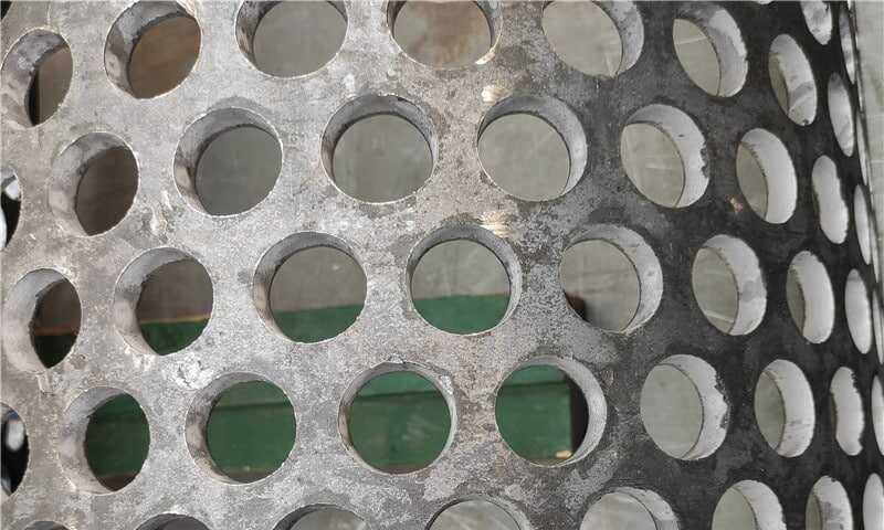
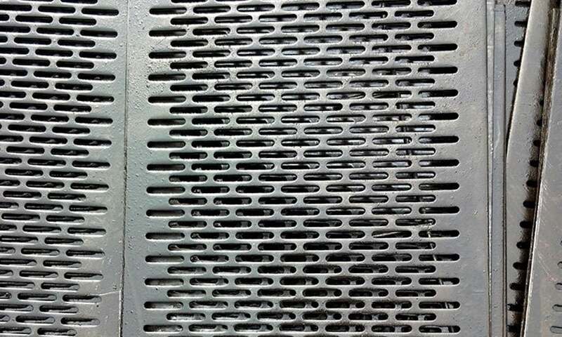
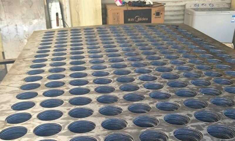
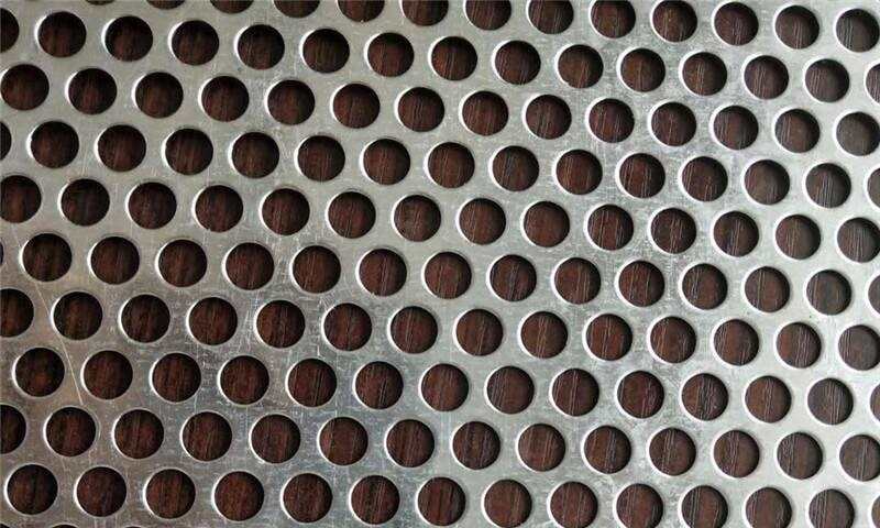
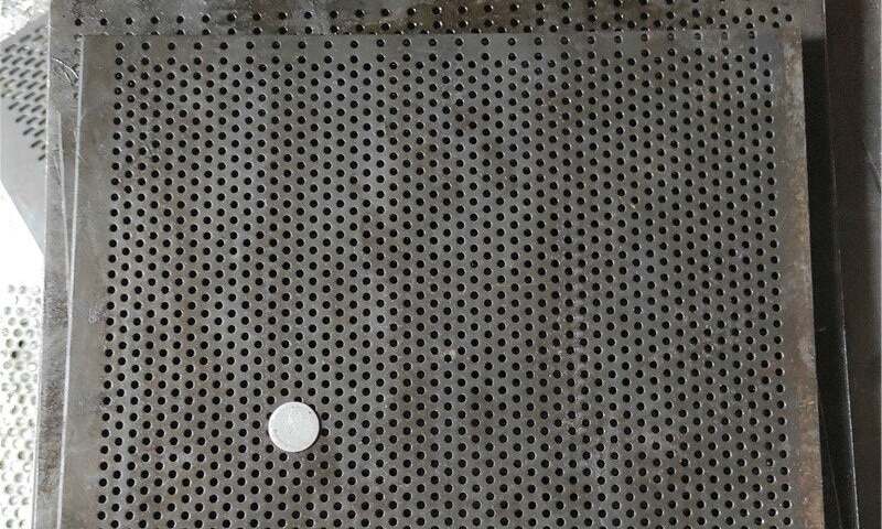
Heavy Duty Perforated Plates
Need a thick perforated plate made to drawing? Our program supports 2.75–30mm thickness, up to 6000×1500mm, with round/square/hex/slotted patterns, plus cut-to-size and surface protection for industrial installations.
How to convert design requirements into thickness (step-by-step)
- Define the worst-case applied load (kN or kN/m²) and whether it’s concentrated or distributed.
- Measure the unsupported span and identify support details (continuous, simply supported, cantilever).
- Select a candidate material (yield strength and elastic modulus affect required thickness).
- Perform a simple bending check or deflection check: ensure deflection under working load stays within allowable limits (typical industrial deflection limits are L/200 to L/500 depending on service).
- If holes/slots remove a significant portion of area (>20–30% open area), increase thickness or reduce span.
- Add corrosion allowance or surface treatment specifications as needed.
Installation & fabrication considerations
- Welding versus bolting: welded edges effectively increase stiffness; bolted edges with gaps must assume lower edge restraint.
- Stiffeners: adding transverse stiffeners can allow a thinner plate to achieve acceptable deflection, which is often cheaper than moving to the next thicker gauge.
- Edge trimming and hole orientation: punching near edges reduces capacity; maintain minimum edge distances per fabrication standard.
- Handling and transport: very thick perforated plates (≥16 mm) are heavy — design pick points and handling fixtures into the plan.
Common mistakes (and how to avoid them)
- Specifying thickness by sight or “rule-of-thumb” only. Always quantify loads and spans and run a deflection check.
- Ignoring hole open area. Two plates with the same nominal gauge but different hole sizes/centers will behave differently.
- Confusing material grade with thickness. High-strength alloys allow some weight reduction, but hole pattern and geometry control stiffness more directly.
- Assuming welded supports eliminate the need for thicker plate — weld quality and fatigue can still govern thickness choice.
- Failing to consider concentrated point loads (forklift wheels, machinery feet). Concentrated loads often dictate local reinforcement or thicker plate.
Practical examples
- Conveyor catwalks carrying personnel only (span 400 mm, UDL 2 kN/m²): 4–6 mm with close-spacing supports or 6–8 mm if supports are wider.
- Equipment base with concentrated feet (150×150 mm pads, 5 kN per foot): start at 8–12 mm and add local backing plate or stiffener to spread the load.
- Abrasive, impact-prone environments: prefer thicker gauges (≥12 mm) in high-wear zones and consider high-manganese options for survivability.
Final checklist before ordering
- Confirm worst-case load scenarios (live, dead, dynamic, impact).
- Confirm unsupported span and support condition drawings.
- Confirm hole pattern, open area percentage and punch direction.
- Confirm material grade and surface treatment.
- Decide if local stiffeners or backing plates are required.
- Prepare an installation note (welding, bolting torque, edge support) for the fabricator.
For buying and detailed fabrication options, reference the product specifics and custom gauge options while you finalize design: consider comparing manufacturer suggested thicknesses for similar load/span cases and consult fabrication services for on-site fitting and welding. See also heavy-duty perforated plate options when confirming order details.
This guide uses engineering-first terminology and practical checks engineers, contractors and procurement specialists commonly use. If you want, I can convert these rules into a one-page specification checklist you can attach to RFQs.