Pitch, Bridge (Ligament) and Edge Margin — why they matter
A perforated plate’s load capacity and long-term durability come from three geometric elements: the hole pitch (center-to-center spacing), the bridge or ligament between holes, and the edge margin (distance from perforation pattern to the panel edge or a mounting/weld zone). When you change one of these three, you change how the panel carries tension, shear and bending loads.
Simple schematic (conceptual)
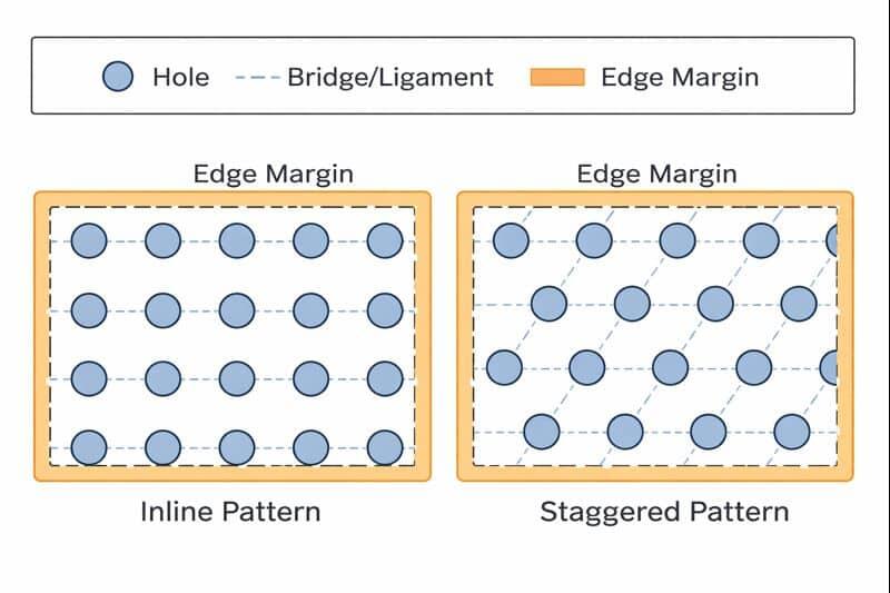
Where the strength actually comes from
- The bridge (ligament) carries local tensile and shear loads. A wider ligament increases local capacity and reduces stress concentration at hole edges.
- The unperforated webs (continuous strips of material between rows) transmit bending and in-plane loads over longer spans. Pattern geometry controls web continuity.
- The edge margin provides anchorage for fasteners, welds or bending operations — it prevents edge fracture and distributes concentrated loads into the plate.
Engineers typically describe these elements using: hole diameter (D), center-to-center pitch (P), ligament/bridge width (B = P − D), and margin (M). Specifying those four values plus pattern (inline vs staggered) gives a fabricator what they need to quote and produce.

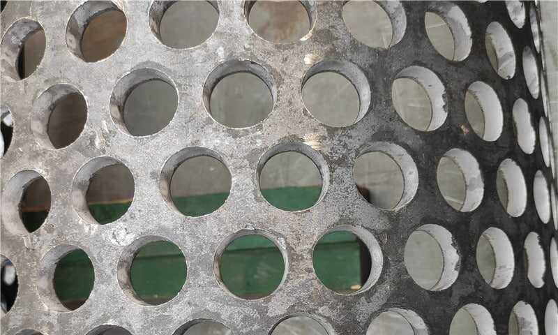
Heavy Duty Perforated Plates
Need a thick perforated plate made to drawing? Our program supports 2.75–30mm thickness, up to 6000×1500mm, with round/square/hex/slotted patterns, plus cut-to-size and surface protection for industrial installations.
How load direction matters
If the applied load is parallel to a row of holes, aligned (inline) holes are more likely to create continuous weak lines. If the load is multi-directional or bending dominates, a staggered pattern often performs better because it interrupts continuous stress paths.
Pitch vs. open area vs. strength — the tradeoffs
- Increasing pitch (bigger P) for a fixed hole size increases bridge width (B) and strength but reduces open area.
- Increasing hole size for a fixed P increases open area but reduces ligament width and local capacity.
- Staggered (offset) patterns typically allow higher open area for the same ligament width compared with inline (straight) patterns because staggered holes avoid collinear ligament removal.
Bullet list — pattern comparisons:
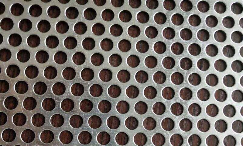
- Staggered (offset / hex)
- Better distribution of stress, higher usable open area at equal ligament width.
- Preferred for panels that must remain stiff under multi-directional loads.
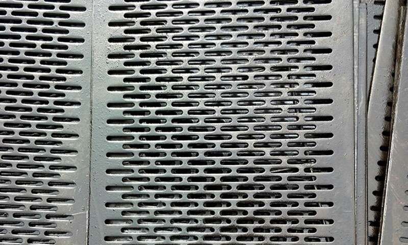
- Inline (straight)
- Simpler layout and punching tooling, slightly better for filtration/flow alignment in some cases.
- May create weak lines under unidirectional loads.
Practical design guidance (rules of thumb and experience)
- Start by defining the service load and direction (tension, shear, bending, abrasion). That will drive whether stiffness or maximum open area is the priority.
- Use the hole diameter and pitch to compute ligament width B = P − D; treat ligament width as the primary control for local strength. As a practice approach: keep ligament width at least on the same order as plate thickness for heavy-gauge panels; increase B when the plate carries high tensile loads or when hole rows are aligned with the load. (This is a guideline, not a guaranteed capacity value.)
- Prefer staggered patterns when you need higher open area without sacrificing ligament width. Use inline patterns when flow orientation or visual alignment is critical.
- Respect an unperforated edge margin for mounting and handling — do not perforate right up to the required fastener/weld zone.
- For fabrication operations (bending, welding), communicate the margin and any required hard zones (solid zones without perforation) up front.

Spec checklist for procurement and engineering (what to include in a drawing/spec)
- Intended material and thickness (e.g., high-manganese steel, 6 mm)
- Hole geometry (shape and nominal diameter)
- Pattern type: staggered (offset) or inline (straight)
- Pitch (center-to-center) in two directions if non-isotropic
- Calculated ligament/bridge width (B = P − D) and minimum acceptable B
- Edge margin (M) and location of mounting/weld zones
- Open area target (if ventilation/filtration is a requirement)
- Tolerances, finish, and any flattening/leveling requirements after punching
Example specification language (engineer-friendly)
- “Perforation: 10 mm diameter holes, staggered pattern, 20 mm pitch (C-C) longitudinal, 18 mm pitch transverse, resulting ligament width not less than 8 mm. Unperforated edge margin 25 mm all around for fasteners and welds. Material: heavy gauge SXXX to X tolerance. See heavy duty perforated plates for typical material grades and fabrication notes.”
If your project moves toward thicker panels or very low open-area designs, also call out bending and welding allowances explicitly and consider flatness control after perforation. For thicker panels you might write: “For thicker panels and heavy load cases, consider the available options for heavy gauge perforated plate construction and reinforcement.”
Quick takeaways
- Strength is controlled by ligament width, web continuity and edge margin — not just hole size.
- Staggered patterns generally give a better strength/open-area tradeoff than inline patterns.
- Always specify pitch, hole size, ligament width and margin together — give the fabricator a single source of truth so there are no surprises.
Numbered checklist before you issue a PO:
- Confirm primary load type and direction.
- Lock hole size and pattern (staggered vs inline).
- Specify pitch and compute B = P − D; set minimum acceptable B.
- Define edge margin and solid zones for fasteners/welds.
- Ask the vendor for a production sample or small test panel if strength or flatness is critical.