


Choosing the correct heavy duty perforated plate hole size is one of the single most important decisions for a functional, durable perforated part. Hole diameter, pitch (center-to-center spacing), and pattern control the plate’s stiffness, wear behaviour, open area and manufacturability. For heavy-duty, load-bearing applications you want a solution that balances structural performance with reliable, cost-effective production.

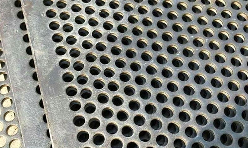
Heavy Duty Perforated Plates
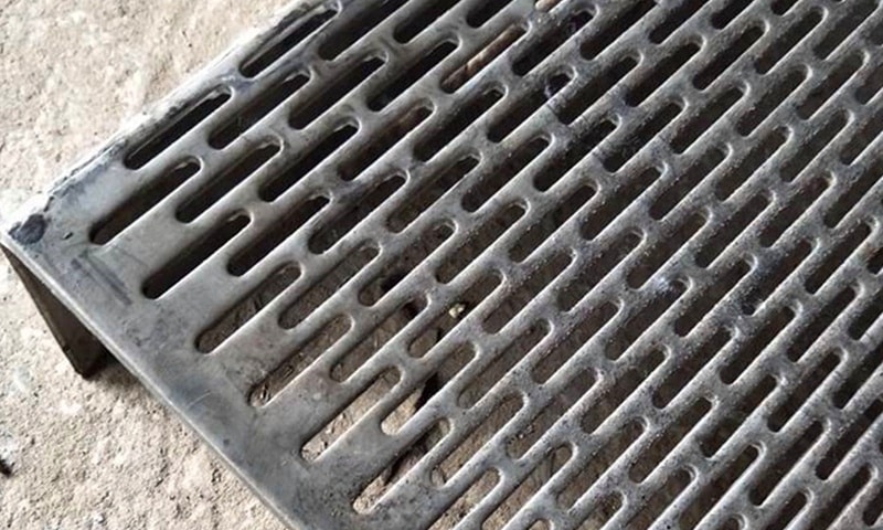
Need a thick perforated plate made to drawing? Our program supports 2.75–30mm thickness, up to 6000×1500mm, with round/square/hex/slotted patterns, plus cut-to-size and surface protection for industrial installations.
Key manufacturing rules of thumb
- Minimum hole diameter vs. plate thickness
- A widely accepted rule of thumb is that hole diameter should not be smaller than the plate thickness; many manufacturers recommend a 1:1 ratio or slightly larger for carbon steels and aluminium. For harder materials (stainless steels, high-strength alloys) allow extra margin or consult tooling specialists.
- Minimum metal “bridge” (land) between holes
- Typical guidance: bridge width ≥ material thickness. Tight bridges increase the risk of rupture, distortion and loss of flatness.
- Pattern choice affects stiffness and open area
- A staggered (60° triangular) layout gives higher rigidity and open area for the same hole size than a straight-line grid.
Risks when holes are too small or too dense
1. Deformation and loss of flatness
- Closely spaced or very small holes concentrate cutting forces and reduce the effective cross-section. Thick plates with many small holes are prone to warping, edge waves and reduced load capacity.
- Practical consequence: extra machining or flattening operations, or the need for stiffer (and more expensive) material.
2. Excessive burrs and poor edge quality
- Small-diameter punching in thick plate produces larger burrs on the die side, requiring secondary deburring or grinding if a clean edge is required.
- Burr control also raises production time and cost.
3. Tooling wear and higher scrap risk
- Punching holes where diameter ≲ thickness increases shear on punches and dies; tool breakage or rapid dulling becomes likely. Frequent tool maintenance increases lead time and part cost.
4. Cost escalation and process limits
- Very small holes in thick plate may be impossible or uneconomic to punch; alternatives such as laser, waterjet, or drilling add per-piece cost and limit production throughput.
- Extremely dense perforations can push you into slower processes or subdivide the work (welding smaller panels), both of which raise assembly cost.
Practical selection checklist (3–300mm holes)
- Define functional needs first (load, wear, drainage, filtration, airflow).
- Match hole diameter to plate thickness:
- For common carbon steel: target hole Ø ≥ plate t (1:1) as a starting point.
- For stainless or high-strength alloys: increase the ratio or discuss with the supplier.
- Pick a pattern for stiffness: triangular staggered for strength and higher open area; straight for visual alignment.
- Maintain minimum bridge = plate thickness (or greater if vibrations or heavy impact expected).
- Consider open-area requirements vs. remaining cross-section — more holes = less material to carry load.
- If hole Ø < plate t or density is very high, plan for secondary operations (deburring, stress-relief, leveling) or alternative cutting methods.
When to switch production methods
- Punching is fast and economical for many hole sizes up to moderate diameters when hole Ø ≥ thickness and patterns are standard.
- For very small holes in very thick plates, or for large holes (toward the upper end of 3–300mm) where punching becomes impractical, consider:
- Laser or plasma cutting for complex shapes and small runs.
- Waterjet or CNC drilling for large Ø holes or holes through very thick sections.
- Each method changes lead time, tolerances and edge quality — factor those into procurement decisions.
Quick design tips to reduce risk and cost
- Use slightly larger hole diameters where functionality permits — a modest increase often reduces tooling wear and scrap significantly.
- Standardize one or two patterns across parts to reduce tooling complexity.
- Add a small unperforated border (edge margin) to preserve mounting strength and flatness.
- Specify required edge condition (deburr / as-punched) up front to avoid surprises in quotes.
Checklist for technical enquiries to your factory partner
- Material grade and thickness (specify exact t).
- Required hole diameter and allowed tolerance.
- Pattern type (triangular/staggered or straight) and pitch.
- Functional requirements (load, wear, filtration, safety).
- Expected panel size and acceptable flatness/twist limits.
- Required finish (deburring, surface treatment).
Conclusion — practical balance wins
In heavy-duty, thick-gauge perforated work the practical choice is a balance: choose hole diameters and spacing that meet function while staying within proven manufacturing rules (hole Ø ≈ or > plate t and bridge ≥ t). When a design pushes those limits, expect secondary operations or alternative cutting methods — and plan cost/time accordingly.
For proven, heavy-duty patterns and custom thick-plate solutions, see our range of heavy duty perforated plates and request advice to specify a thick perforated plate that meets your load and durability requirements.


